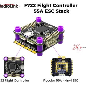
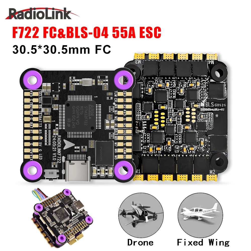
Betaflight F405 F4 V3 PLUS Flight Controller with 60A 4-in-1 ESC Stack
The Betaflight F405 V3 Plus FPV Flight Controller with 60A 4-in-1 ESC Stack is a complete high-performance power and control solution for FPV racing, freestyle, and long-range drones. This stack combines a powerful STM32F405 flight controller with a heavy-duty 60A BLHeli 4-in-1 ESC, giving you smooth flight control and reliable high-current motor drive in one compact system.
The F405 flight controller is fully compatible with Betaflight firmware, allowing easy setup, tuning, and firmware updates. It supports popular receiver protocols like SBUS, iBUS, CRSF (ELRS), and more. Multiple UART ports make it easy to connect GPS, VTX, telemetry, and other FPV accessories.
The 60A 4-in-1 ESC supports 2S to 6S LiPo batteries and delivers strong, stable power even for high-KV motors and aggressive flying styles. BLHeli firmware with DShot support ensures fast throttle response, smooth motor control, and efficient performance.
With a compact stack design, this combo reduces wiring, saves space, and improves reliability, making it perfect for clean and professional FPV builds.
Betaflight F405 V3 PLUS Flight Controller & 60A 4 in 1 ESC Stack Instruction Manual
1. Introduction
This manual provides detailed instructions for the installation, operation, and maintenance of the TEARCKEP F405 F4 V3S PLUS Flight Controller and V3 4-in-1 BLS ESC Stack. Designed for RC FPV racing drones, this high-performance stack offers advanced features for optimal flight control and power management.
Drive Signal Support: DShot150-300-600 / Multishot / Oneshot / PMW
Current Sensor: Supports
Size: 41 * 39 * 5mm
Weight: 15g
3. Package Contents
Depending on your selection, the package may include:
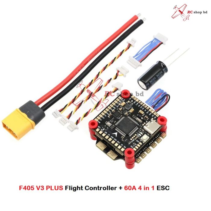
1x F405 V3 PLUS Flight Controller (FC)
1x 60A 4-in-1 Electronic Speed Controller (ESC)
1x Connecting Cable (various types for FC to ESC, receiver, etc.)
4x Rubber Damping Columns (M3-7)
1x XT60 Power Cable (with capacitor)
Additional signal wires for various connections
1x Electrolytic Capacitor
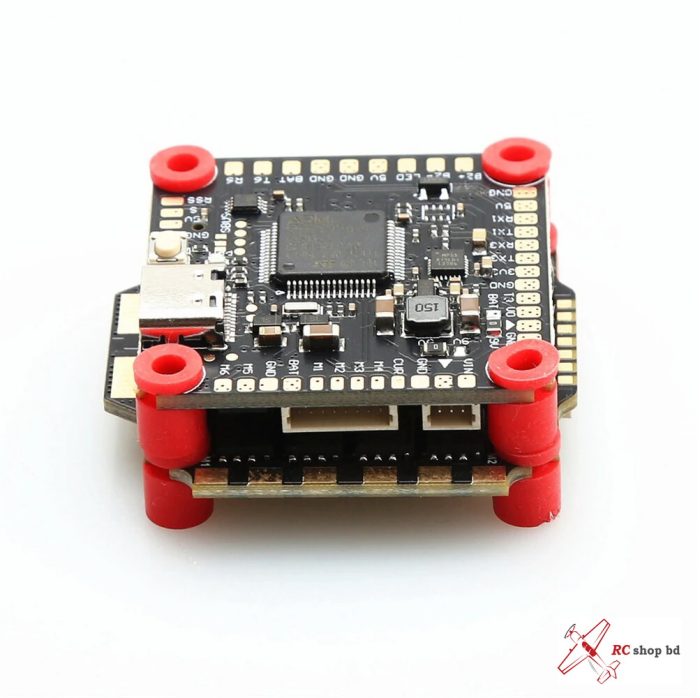
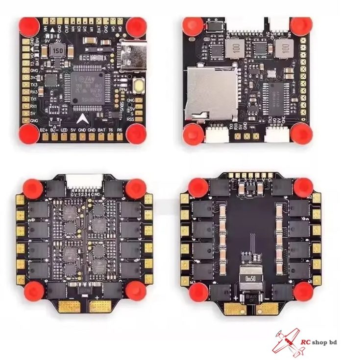
Figure 3.1: Overview of the Flight Controller and ESC Stack components, including cables and mounting hardware.Figure 3.2: Detailed view of the F405 V3 PLUS Flight Controller board.Figure 3.3: Detailed view of the V3 4-in-1 BLHELI-S ESC board.
4. Setup and Installation
Important Installation Precaution:
Always pay close attention to the input voltage pads and ensure correct polarity (positive and negative electrodes) when making connections, especially when not using pre-wired flat cables. Incorrect wiring can cause irreversible damage.
4.1 Physical Installation
The Flight Controller and ESC are designed for a 30.5×30.5mm mounting pattern.
Use the provided M4 rubber damping columns for mounting to reduce vibrations, which can improve flight performance and gyroscope accuracy.
Carefully stack the FC on top of the ESC, aligning the mounting holes.
4.2 Wiring Diagram and Connections
Refer to the schematic diagram below for common wiring connections. This diagram illustrates how to connect various peripherals such as VTX, GPS, Camera, and Receiver to the F405 V3 PLUS Flight Controller.
Figure 4.1: Schematic diagram for common flight control wiring. Note the VTX and GPS share TX3, selectable via software.
Power Connection: Connect your LIPO battery (2-6S) to the BAT+ and BAT- pads on the ESC. Ensure the electrolytic capacitor is soldered to the main battery pads for ripple filtering.
Motor Connections: Solder your motor wires to the corresponding M1-M4 pads on the ESC.
FC to ESC Connection: Use the provided connecting cable to link the FC to the 4-in-1 ESC. Ensure correct pin alignment.
Receiver Connection:
For SBUS/CRSF/IBUS/PPM receivers, connect to RX1 and TX1 pads.
For 3.3V SPEKTRUM satellite receivers, connect to the 3.3V, GND, and RX6 pads. The default receiver input is UART6.
Video Transmitter (VTX) & GPS: The VTX and GPS modules can share the TX3 port. You will need to configure which device uses TX3 in your flight control software (e.g., Betaflight).
VTX: Connect to 5V/9V, GND, and VTX pads.
GPS: Connect to 5V, GND, TX3, and RX3 pads.
Camera: Connect your FPV camera to the 5V/9V, GND, and CAM pads.
LED Strip: Connect compatible LED strips to the 5V, GND, and LED pads.
Buzzer: Connect a buzzer to the B+ and B- pads for audible alerts.
MicroSD Card: Insert a MicroSD card into the dedicated slot for black box logging.
USB Port: The USB Type-C port is used for connecting to a computer for configuration and firmware updates.
5. Operating Instructions
5.1 Firmware and Configuration
The Flight Controller comes pre-loaded with OMNIBUSF4SD/BF/INAV firmware, which is upgradable.
Connect the FC to your computer via the USB Type-C port.
Open the Betaflight Configurator (or INAV Configurator, depending on your firmware).
Ensure the correct COM port is selected and click “Connect”.
OSD Configuration: The drag-and-drop OSD can be configured directly within Betaflight to display flight data on your FPV feed.
Dshot Support: The ESC supports DShot150-300-600, Multishot, Oneshot, and PMW protocols. DShot is recommended for optimal performance and can be selected in Betaflight.
Receiver Setup: Configure your receiver type (e.g., SBUS, CRSF) in the Betaflight Receiver tab. Ensure the correct UART is selected (e.g., UART6 for default receiver input).
Motor Calibration: Perform motor calibration through the ESC configuration software (e.g., BLHeliSuite32 for BLHeli_32 ESCs, or Betaflight Passthrough for BLHeli_S ESCs) if necessary.
5.2 Flight Preparation
Before each flight, ensure all connections are secure and free from damage.
Verify battery voltage and propeller direction.
Check your FPV feed and OSD for correct information display.
Always perform a pre-flight check of your drone’s controls and arming sequence in a safe environment.
6. Maintenance
Regular Inspection: Periodically inspect the FC and ESC for any signs of physical damage, loose connections, or solder joint issues.
Cleaning: Keep the boards clean from dust, dirt, and debris. Use compressed air or a soft brush. Avoid using liquids directly on the electronics.
Firmware Updates: Regularly check for and apply firmware updates for both the FC (Betaflight/INAV) and ESC (BLHeli_S) to benefit from performance improvements and bug fixes.
Storage: When not in use, store the components in a dry, anti-static environment.
7. Troubleshooting
No Power/No Lights:
Check battery connection and voltage.
Verify main power cable polarity and solder joints.
Inspect for any short circuits on the board.
Motors Not Spinning/Erratic Behavior:
Ensure ESC is properly connected to the FC.
Check motor wire connections to the ESC.
Verify ESC firmware and settings (e.g., DShot protocol).
Recalibrate ESCs if necessary.
No Receiver Input:
Confirm receiver is powered and bound to your radio.
Check receiver wiring to the FC (RX1/TX1 or RX6).
Verify receiver type and UART settings in Betaflight.
OSD Not Displaying:
Ensure FPV camera and VTX are correctly wired.
Check OSD settings in Betaflight.
Flight Instability:
Verify FC mounting is secure and free from excessive vibration (check rubber damping columns).
Review PID settings in Betaflight.
Ensure propellers are balanced and undamaged.
8. User Tips
Start with Default Settings: For initial setup, it’s often best to start with the default Betaflight/INAV settings for your frame size and then fine-tune gradually.
Backup Your Configuration: Always save a backup of your Betaflight/INAV configuration (CLI dump) before making significant changes or firmware updates.
Heat Shrink Protection: Consider using heat shrink tubing on exposed solder joints or connections for added protection against shorts and environmental factors.
Proper Soldering: Ensure all solder joints are clean, strong, and free of bridges to prevent electrical issues.